
Introduction of Basics of Software Engineering Designs & Life Cycle Models
Software engineering is a systematic approach to the development, operation, maintenance, and retirement of software. It involves the application of engineering principles to software development in order to ensure that the software is reliable, efficient, maintainable, and meets user requirements. Key components of software engineering include software design and software life cycle models.
Basics of Software Engineering Designs
1. Software Design
Software design is the process of defining the architecture, components, interfaces, and other characteristics of a system or its components. It serves as a blueprint for the software development process.
Types of Software Design
- Architectural Design: Defines the overall structure of the system and the interactions between the different components. It focuses on high-level design decisions such as system organization and communication protocols.
- Detailed Design: Focuses on the implementation details of each component, including data structures, algorithms, and interfaces.
- User Interface Design: Involves designing the interaction between the user and the system, ensuring the software is intuitive and easy to use.
- Component Design: Specifies how individual components of the software will be implemented and how they will interact with other components.
Principles of Software Design
- Modularity: Breaking down a system into smaller, manageable parts or modules that can be developed and tested independently.
- Abstraction: Simplifying complex systems by focusing on the essential features while hiding the implementation details.
- Encapsulation: Bundling data and methods that operate on the data within a single unit or class, restricting access to some components.
- Separation of Concerns: Dividing a program into distinct sections, each addressing a specific concern or functionality.
- Cohesion and Coupling:
- Cohesion: Measures how closely related the functions within a module are. High cohesion is desirable as it indicates that a module is focused on a single task.
- Coupling: Refers to the degree of interdependence between modules. Low coupling is desirable as it allows modules to be changed independently.
2. Software Life Cycle Models
Software life cycle models describe the phases involved in the development of a software product, from initial concept to deployment and maintenance. These models help organize and manage the software development process.
Common Software Life Cycle Models
- Waterfall Model: A linear and sequential approach where each phase must be completed before the next phase begins. It is simple and easy to understand but inflexible in accommodating changes.Example: Building a house follows a waterfall model. You need to complete the foundation before building walls, and the walls before the roof. Changes after completion of each phase can be costly and difficult.
- V-Model (Validation and Verification Model): An extension of the waterfall model where each development phase is associated with a corresponding testing phase. It emphasizes testing and validation at every stage.Example: Manufacturing a car follows the V-model, where each component (engine, chassis, etc.) is tested and validated individually before integration.
- Incremental Model: Develops the system in increments or small parts, with each increment adding new functionality. It allows for partial implementation and gradual refinement.Example: A restaurant menu that starts with a few items and gradually expands based on customer feedback and demand.
- Iterative Model: Develops a system through repeated cycles (iterations), allowing for refinement and improvements based on user feedback.Example: Creating a sculpture involves iterative refinement, where the artist makes rough outlines and refines the sculpture over several iterations.
- Spiral Model: Combines elements of iterative and incremental models with a focus on risk analysis. It allows for continuous refinement and risk assessment throughout the development process.Example: Developing a new drug involves multiple phases of testing, evaluation, and risk assessment to ensure safety and efficacy.
- Agile Model: Emphasizes flexibility, collaboration, and customer feedback. Development is carried out in small, iterative cycles called sprints, allowing for rapid adaptation to changes.Example: Planning a wedding involves agile-like flexibility, where the couple makes adjustments based on preferences and feedback from family and vendors.
Real-Life Example: Developing an E-commerce Website
- Requirements Gathering:
- Understand user needs and business goals (e.g., online shopping platform for electronics).
- Design Phase:
- Architectural Design: Define the overall structure of the website, including the server, database, and client-side components.
- User Interface Design: Design the layout, navigation, and aesthetics of the website to ensure a user-friendly experience.
- Development Phase:
- Incremental/Agile Approach: Develop core features such as product catalog, shopping cart, and payment gateway in increments or sprints, incorporating feedback from stakeholders.
- Testing Phase:
- V-Model Approach: Test each component (e.g., payment gateway) and validate it against user requirements before integration.
- Deployment Phase:
- Launch the website and monitor its performance, ensuring it meets user expectations.
- Maintenance Phase:
- Continuously update the website, fix bugs, and add new features based on user feedback and changing market trends.
Conclusion
Software engineering design and life cycle models provide a structured approach to software development, ensuring that the final product meets user requirements and quality standards. By applying these principles and models, software engineers can create reliable, efficient, and user-friendly software solutions tailored to specific needs.
Evolution and impact of Software Engineering
The field of software engineering has undergone significant evolution since its inception, driven by the increasing complexity of software systems and the demand for reliable, efficient, and user-friendly applications. This evolution has had a profound impact on how software is developed, maintained, and integrated into various industries.
Evolution of Software Engineering
1. Early Days (1950s-1960s)
- Problem: In the early days of computing, software development was ad-hoc, with little formal structure or methodology. As computers were primarily used for scientific and military purposes, software systems were simple and often developed by individuals or small teams.
- Challenges:
- Lack of formal development processes.
- High rates of errors and bugs.
- Limited understanding of software design and architecture.
- Key Development:
- The term “software engineering” was coined during the 1968 NATO Software Engineering Conference, highlighting the need for more disciplined and structured approaches.
2. Structured Programming (1970s)
- Problem: As software systems grew in complexity, the limitations of ad-hoc development became apparent, leading to the “software crisis” characterized by projects running over budget, behind schedule, and with poor quality.
- Solution:
- Structured Programming: Introduced principles such as modularization, top-down design, and the use of structured control flow constructs (e.g., loops and conditionals) to improve code clarity and maintainability.
- Impact:
- Improved code readability and reusability.
- Reduction in errors and bugs.
- Greater emphasis on planning and design before coding.
3. Introduction of Software Development Models (1980s)
- Problem: The need for more formalized processes to manage growing software complexity and ensure project success.
- Solution:
- Development of software life cycle models, including the Waterfall Model, Spiral Model, and V-Model.
- Waterfall Model: Linear and sequential approach with distinct phases (requirements, design, implementation, testing, deployment).
- Spiral Model: Emphasizes iterative development and risk management.
- Impact:
- Improved project management and predictability.
- Formalized documentation and design processes.
- Early detection and mitigation of risks.
4. Emergence of Object-Oriented Programming (1990s)
- Problem: The need for better ways to manage software complexity and enhance code reuse.
- Solution:
- Object-Oriented Programming (OOP): Introduced concepts such as classes, objects, inheritance, and polymorphism to model real-world entities and relationships.
- Unified Modeling Language (UML): Provided a standardized way to visualize and design object-oriented systems.
- Impact:
- Enhanced code modularity and reusability.
- Improved system design and modeling.
- Facilitated the development of complex systems with reusable components.
5. Rise of Agile and Lean Practices (2000s)
- Problem: The need for more flexible and adaptive development approaches to respond to changing user requirements and market conditions.
- Solution:
- Agile Methodologies: Emphasize iterative development, customer collaboration, and adaptability. Key frameworks include Scrum, Kanban, and Extreme Programming (XP).
- Lean Software Development: Focuses on optimizing efficiency and eliminating waste.
- Impact:
- Faster delivery of software products.
- Improved customer satisfaction and collaboration.
- Greater ability to adapt to changing requirements and market conditions.
6. Modern Software Engineering (2010s-Present)
- Problem: The need to manage the growing scale and complexity of software systems, including cloud computing, big data, and artificial intelligence.
- Solution:
- DevOps: Integrates development and operations to streamline deployment and maintenance processes.
- Microservices Architecture: Breaks down applications into smaller, independent services that can be developed, deployed, and scaled independently.
- Continuous Integration/Continuous Deployment (CI/CD): Automates testing and deployment to ensure rapid and reliable software delivery.
- Impact:
- Increased development speed and efficiency.
- Improved software quality and reliability.
- Enhanced scalability and flexibility of software systems.
Impact of Software Engineering
1. Economic Impact
- Increased Productivity: Improved software engineering practices have led to increased productivity and efficiency in software development, reducing costs and time-to-market.
- Job Creation: The demand for skilled software engineers has created numerous job opportunities and contributed to economic growth.
- Innovation: Software engineering has enabled the development of innovative products and services, driving technological advancements across various industries.
2. Social Impact
- Improved Quality of Life: Software applications have improved healthcare, education, communication, and entertainment, enhancing overall quality of life.
- Digital Transformation: Software engineering has facilitated the digital transformation of businesses and industries, enabling them to leverage technology for competitive advantage.
- Access to Information: The internet and software applications have democratized access to information and resources, empowering individuals and communities.
3. Environmental Impact
- Energy Efficiency: Advances in software engineering have led to more energy-efficient computing solutions, reducing the environmental impact of technology.
- Sustainability: Software solutions have enabled the development of sustainable practices in various industries, such as energy management, transportation, and agriculture.
4. Challenges and Considerations
- Security and Privacy: The increasing reliance on software systems has raised concerns about security vulnerabilities and data privacy.
- Ethical Considerations: Software engineers must consider ethical implications, such as bias in algorithms and the impact of automation on employment.
- Complexity Management: As software systems continue to grow in complexity, managing and maintaining them remains a significant challenge.
Conclusion
The evolution of software engineering has transformed the way software is developed and has had a profound impact on society, the economy, and the environment. By adopting best practices and embracing new technologies, software engineers continue to drive innovation and address the challenges of the modern world.
Solution to the software Crisis
What is software Crisis
The software crisis is a term that emerged in the late 1960s to describe the challenges and problems faced by the software industry as computer systems became more complex and widespread. As the demand for software grew, developers struggled to produce reliable, efficient, and maintainable software on time and within budget. This led to numerous issues that collectively became known as the software crisis.
Causes of the Software Crisis
1. Lack of Formal Methods
- Software development was often approached in an ad-hoc manner without formal methodologies or structured processes.
2. Rapid Technological Advancements
- The fast pace of technological change outstripped the ability of developers to adapt and apply new techniques and tools.
3. Inadequate Tools and Techniques
- Early software development lacked sophisticated tools and techniques for design, testing, and project management.
4. Insufficient Testing
- Limited testing practices led to the release of software with significant defects and vulnerabilities.
5. Poor Communication
- Ineffective communication between stakeholders, developers, and users resulted in misunderstandings and misaligned goals.
The software crisis of the late 1960s and 1970s highlighted the challenges faced by the software industry in developing complex software systems. These challenges included issues like project delays, cost overruns, poor quality, and maintenance difficulties. In response to these challenges, the field of software engineering evolved significantly, developing new methodologies, tools, and practices to address the software crisis effectively. Here are some of the key solutions that have helped mitigate the problems associated with the software crisis:
Solutions to the Software Crisis
1. Structured Programming
- Description: Structured programming introduced programming techniques that emphasized the use of structured control flow constructs (such as loops, conditionals, and subroutines) to improve code readability, reliability, and maintainability.
- Key Techniques:
- Modularization: Breaking down complex programs into smaller, manageable modules or functions.
- Control Structures: Using loops and conditionals instead of
gotostatements to create clear and logical flow of control. - Top-Down Design: Designing software from a high-level overview down to specific details.
- Impact:
- Reduced complexity and improved code clarity.
- Easier debugging and maintenance.
- Enhanced collaboration among developers through standardized coding practices.
2. Software Development Life Cycle Models
- Description: Formal software development life cycle (SDLC) models provide structured approaches to software development, helping teams plan, execute, and manage projects effectively.
- Common Models:
- Waterfall Model: A linear, sequential approach with distinct phases such as requirements, design, implementation, testing, and deployment. This model is suitable for projects with well-defined requirements.
- V-Model: An extension of the Waterfall Model that emphasizes validation and verification at each stage of development.
- Incremental Model: Builds software in small increments, allowing partial functionality to be delivered early and refined over time.
- Spiral Model: Combines iterative development with risk management, allowing for continuous refinement and risk assessment.
- Agile Model: Emphasizes iterative development, customer collaboration, and adaptability to changing requirements. Key frameworks include Scrum, Kanban, and Extreme Programming (XP).
- Impact:
- Improved project planning and management.
- Better alignment with user requirements and expectations.
- Enhanced risk management and quality assurance.
3. Object-Oriented Programming (OOP)
- Description: OOP is a programming paradigm that uses objects to represent data and behavior, promoting encapsulation, inheritance, and polymorphism.
- Key Concepts:
- Encapsulation: Bundling data and methods within a single unit (class) and restricting access to certain components.
- Inheritance: Allowing new classes to inherit properties and methods from existing classes, promoting code reuse.
- Polymorphism: Enabling objects to be treated as instances of their parent class, allowing for flexible and dynamic code.
- Impact:
- Improved modularity and reusability of code.
- Enhanced ability to model complex systems and real-world entities.
- Greater maintainability and scalability of software systems.
4. Agile Methodologies
- Description: Agile methodologies emphasize flexibility, collaboration, and iterative development. They focus on delivering small, incremental updates to software products, allowing for rapid adaptation to changes.
- Key Frameworks:
- Scrum: Organizes development into fixed-length iterations called sprints, with regular meetings (stand-ups) to track progress and adapt to changes.
- Kanban: Focuses on visualizing the workflow and limiting work in progress to improve efficiency.
- Extreme Programming (XP): Emphasizes practices such as test-driven development, pair programming, and continuous integration.
- Impact:
- Faster delivery of software products and features.
- Improved customer satisfaction through frequent feedback and collaboration.
- Enhanced ability to adapt to changing requirements and market conditions.
5. DevOps Practices
- Description: DevOps integrates development and operations teams to streamline the software delivery process, improve collaboration, and enhance software quality.
- Key Practices:
- Continuous Integration (CI): Automating the integration of code changes from multiple developers into a shared repository.
- Continuous Deployment (CD): Automating the deployment of software to production environments, ensuring rapid and reliable delivery.
- Infrastructure as Code (IaC): Managing and provisioning infrastructure using code, enabling consistent and repeatable environments.
- Impact:
- Increased development speed and efficiency.
- Improved collaboration between development and operations teams.
- Enhanced software quality and reliability through automated testing and deployment.
6. Improved Testing and Quality Assurance
- Description: Emphasizing testing and quality assurance throughout the software development process ensures that software meets user requirements and quality standards.
- Key Techniques:
- Test-Driven Development (TDD): Writing tests before developing code to ensure that functionality is correctly implemented.
- Automated Testing: Using automated tools to execute tests, reducing manual effort and increasing test coverage.
- Continuous Testing: Integrating testing into the development pipeline to identify and address issues early.
- Impact:
- Reduced defects and improved software reliability.
- Faster identification and resolution of issues.
- Greater confidence in software quality and performance.
7. Project Management Practices
- Description: Formal project management practices help software teams plan, execute, and monitor projects effectively, ensuring that they are delivered on time and within budget.
- Key Practices:
- Scope Management: Clearly defining and managing project scope to prevent scope creep and ensure alignment with objectives.
- Risk Management: Identifying, assessing, and mitigating risks to minimize their impact on the project.
- Resource Management: Allocating and managing resources (e.g., personnel, budget, time) effectively to achieve project goals.
- Impact:
- Improved project predictability and control.
- Enhanced ability to manage complex projects and resources.
- Greater alignment with business goals and user requirements.
8. Training and Education
- Description: Providing comprehensive training and education programs for software engineers ensures that they have the necessary skills and knowledge to tackle complex projects.
- Key Strategies:
- Continuous Learning: Encouraging ongoing learning and development through workshops, courses, and certifications.
- Knowledge Sharing: Fostering a culture of collaboration and knowledge sharing within teams and organizations.
- Mentoring and Coaching: Providing mentorship and coaching to junior developers to enhance their skills and experience.
- Impact:
- Increased availability of skilled software engineers.
- Improved ability to manage and execute complex projects.
- Enhanced collaboration and knowledge transfer within teams.
Conclusion
The software crisis underscored the need for a disciplined and systematic approach to software development. By adopting best practices, methodologies, and tools, the software industry has been able to address the challenges of the software crisis and produce reliable, efficient, and user-friendly software solutions. These solutions have paved the way for continued innovation and growth in the field of software engineering, enabling organizations to leverage technology for competitive advantage and success.
Early Computer Programming
Early computer programming marked the beginning of the software development industry. It laid the foundation for the complex software systems we use today. In the early days, programming was a challenging task due to limited hardware capabilities, lack of standardized languages, and primitive development tools. Here’s an overview of the early days of computer programming:
Early Computer Programming
1. Machine Code
- Description: Machine code is the lowest-level programming language, consisting of binary instructions (0s and 1s) that a computer’s central processing unit (CPU) can directly execute.
- Characteristics:
- Directly corresponds to the computer’s hardware architecture.
- Difficult to read, write, and debug due to its binary nature.
- Highly efficient in terms of execution speed and resource usage.
- Impact:
- Machine code was used for the earliest computers, requiring programmers to have an in-depth understanding of hardware.
- Programming was a time-consuming and error-prone process.
2. Assembly Language
- Description: Assembly language is a low-level programming language that uses mnemonic codes and labels to represent machine-level instructions.
- Characteristics:
- Provides a symbolic representation of machine code, making it easier to read and write.
- Requires an assembler to translate assembly language code into machine code.
- Still closely tied to the hardware architecture, offering limited portability.
- Impact:
- Simplified programming compared to machine code, reducing errors and development time.
- Allowed for more sophisticated programs and increased programmer productivity.
3. Early High-Level Programming Languages
- Description: High-level programming languages abstract away the hardware details, allowing programmers to write code in a more human-readable form.
- Notable Early Languages:
- FORTRAN (1957):
- Developed by IBM for scientific and engineering calculations.
- Focused on numerical computation and formula translation.
- Simplified complex mathematical calculations and improved productivity in scientific fields.
- COBOL (1959):
- Developed for business data processing.
- Focused on record handling and file processing.
- Widely adopted in business and government applications, known for its readability and ability to handle large data sets.
- LISP (1958):
- Developed for artificial intelligence research.
- Emphasized symbolic computation and list processing.
- Influenced the development of AI and functional programming paradigms.
- ALGOL (1958):
- Designed as a universal language for algorithm description.
- Introduced structured programming concepts and block structures.
- Influenced many later languages, including Pascal and C.
- FORTRAN (1957):
- Impact:
- Enabled the development of more complex and portable software systems.
- Improved programmer productivity and code maintainability.
- Expanded the scope of programming beyond hardware-specific tasks to domain-specific applications.
4. Development Tools and Environments
- Description: Early development environments were rudimentary, with limited tools for editing, compiling, and debugging code.
- Key Tools:
- Punch Cards: Used to input and store programs, with each card representing a single line of code.
- Assemblers and Compilers: Translated assembly and high-level code into machine code.
- Debuggers: Provided basic tools for identifying and fixing errors in code.
- Impact:
- Programming was often a batch process, with long turnaround times for compiling and testing code.
- Lack of sophisticated tools made debugging and error correction challenging.
5. Early Programming Paradigms
- Procedural Programming:
- Focused on procedures or routines to perform tasks.
- Emphasized structured programming and top-down design.
- Dominated early programming, influencing languages like FORTRAN and COBOL.
- Functional Programming:
- Focused on mathematical functions and immutability.
- Emphasized declarative programming and avoiding side effects.
- Influenced by languages like LISP and later Haskell and Scala.
6. Notable Early Computers
- ENIAC (1945):
- One of the first electronic general-purpose computers.
- Used for calculations in scientific and military applications.
- Programming involved manually setting switches and rerouting cables.
- UNIVAC (1951):
- The first commercially available computer.
- Used for business data processing and scientific calculations.
- Utilized punch cards and magnetic tape for input and output.
- IBM 650 (1954):
- One of the first mass-produced computers.
- Widely used in business and academic settings.
- Supported assembly language programming.
7. Challenges of Early Programming
- Limited Hardware Capabilities:
- Early computers had limited memory and processing power, requiring efficient programming techniques.
- Lack of Standardization:
- Different computers had their own machine code and assembly languages, making software non-portable.
- Manual Input and Output:
- Input and output were often manual, using punch cards and printed output, leading to slow and error-prone processes.
- Error-Prone Development:
- Lack of advanced debugging tools made identifying and fixing errors challenging.
Conclusion
Early computer programming laid the foundation for the modern software industry. Despite the challenges of limited hardware capabilities, non-standardized languages, and primitive tools, early programmers developed innovative solutions that continue to influence software development today. The evolution of programming languages, paradigms, and tools has enabled the creation of complex and sophisticated software systems, driving technological advancements and innovation across industries.
Data Structure-oriented design
Data structure-oriented design is a software design approach that focuses on organizing and structuring data efficiently to solve specific problems. It emphasizes the importance of choosing the right data structures to optimize performance, maintainability, and scalability of software applications. This approach is particularly useful when the efficiency of data access, manipulation, and storage is critical to the application’s success.
Key Concepts of Data Structure-Oriented Design
1. Data Abstraction
- Description: Data abstraction involves defining the data types and structures needed to represent information in a program, hiding the implementation details from the user.
- Benefits:
- Simplifies complex systems by focusing on what data represents rather than how it is stored.
- Enhances code readability and maintainability by providing clear interfaces for data manipulation.
- Example: Abstract data types (ADTs) such as stacks, queues, lists, and trees encapsulate data and operations, providing a consistent interface for users.
2. Efficient Data Structures
- Description: The choice of data structures significantly impacts the efficiency of an application. Efficient data structures optimize data storage, access, and manipulation.
- Common Data Structures:
- Arrays and Linked Lists: Used for storing ordered collections of elements.
- Stacks and Queues: Used for managing collections with specific order constraints (LIFO for stacks, FIFO for queues).
- Trees: Hierarchical data structures used for representing hierarchical relationships and enabling efficient searching and sorting.
- Graphs: Used for representing networks and relationships between entities.
- Hash Tables: Provide fast access and retrieval of data using hash functions.
- Impact:
- Efficient data structures improve the performance of operations such as searching, sorting, and updating data.
- Choosing the right data structure can significantly reduce time and space complexity.
3. Algorithm Efficiency
- Description: Data structure-oriented design involves selecting algorithms that complement chosen data structures to ensure efficient data manipulation.
- Considerations:
- Time Complexity: The amount of time an algorithm takes to complete based on input size.
- Space Complexity: The amount of memory an algorithm uses based on input size.
- Trade-offs: Balancing time and space complexity based on application requirements.
- Example: Using a binary search tree for fast searching and insertion, with algorithms like in-order traversal for ordered data retrieval.
4. Modularity and Reusability
- Description: Designing software using data structures promotes modularity and reusability by encapsulating data and operations into cohesive units.
- Benefits:
- Increases code reusability by allowing data structures to be reused across different parts of an application or in different projects.
- Enhances modularity by dividing a program into independent components, each responsible for specific data operations.
- Example: Implementing a priority queue as a modular component that can be reused in various applications requiring prioritized task scheduling.
5. Scalability and Performance
- Description: Data structure-oriented design emphasizes scalability and performance by optimizing data handling for growing datasets and increasing load.
- Considerations:
- Dynamic Data Structures: Use dynamic structures like linked lists or resizable arrays to handle varying data sizes efficiently.
- Concurrent Data Structures: Implement thread-safe data structures to support concurrent access in multi-threaded environments.
- Example: Using concurrent data structures like concurrent hash maps to handle large-scale, concurrent data access in web applications.
Data-Flow Oriented Design
Data-flow oriented design is a software design approach that emphasizes the flow of data through a system. It focuses on understanding how data is transformed as it moves from input to output and how it interacts with different processing components. This design paradigm is particularly useful for applications where data processing is the primary concern, such as data analysis, real-time systems, and signal processing.
Key Concepts of Data-Flow Oriented Design
1. Data Flow Diagrams (DFDs)
- Description: Data flow diagrams are graphical representations that illustrate the flow of data within a system. They show how data is input, processed, and output by different components.
- Components:
- Processes: Represent data transformation activities. Typically shown as circles or ovals in DFDs.
- Data Stores: Represent storage locations for data within the system, depicted as open rectangles.
- Data Flows: Arrows indicating the movement of data between processes, data stores, and external entities.
- External Entities: Represent sources or destinations of data outside the system, shown as rectangles.
- Levels of DFDs:
- Level 0 (Context Diagram): Provides a high-level overview of the system and its interaction with external entities.
- Level 1: Breaks down the context diagram into more detailed processes and data flows.
- Level 2 and Beyond: Further decomposes processes into finer details, providing a deeper understanding of the system.
- Example:
- An e-commerce system DFD might show processes like user registration, product search, order processing, and payment handling, with data flows between these processes and data stores like user databases and product catalogs.
2. Data Transformations
- Description: Data transformations describe how data is processed and modified as it flows through the system.
- Types of Transformations:
- Input Processing: Converting raw input data into a format suitable for processing.
- Computation: Performing calculations, aggregations, or other data manipulations.
- Data Validation: Checking data for accuracy, completeness, and validity.
- Output Generation: Formatting data for presentation or storage.
- Example:
- In a payroll system, data transformations may include calculating employee salaries, tax deductions, and generating paychecks.
3. Pipelines and Filters
- Description: Pipelines and filters are design patterns that represent data processing as a sequence of independent stages (filters) connected by data channels (pipelines).
- Characteristics:
- Filters: Independent processing components that transform input data into output data.
- Pipelines: Connect filters in a sequence, allowing data to flow from one filter to the next.
- Example:
- In a data processing application, a pipeline might consist of filters for data extraction, transformation, and loading (ETL), each responsible for a specific data processing task.
4. Event-Driven Processing
- Description: Event-driven processing involves reacting to data events as they occur, triggering data transformations and processing in response.
- Characteristics:
- Event Sources: Generate events that indicate changes in data or system state.
- Event Handlers: Respond to events by executing specific actions or processing tasks.
- Event Queues: Manage and coordinate events for asynchronous processing.
- Example:
- In a stock trading system, an event-driven approach might process real-time market data updates, triggering trades based on predefined rules.
5. Data Flow Architecture
- Description: Data flow architecture is a system design approach that focuses on defining how data moves between processing components and storage systems.
- Components:
- Input Sources: Collect and feed data into the system for processing.
- Processing Units: Transform and manipulate data based on defined rules and logic.
- Output Sinks: Deliver processed data to external systems or users.
- Example:
- In a weather monitoring system, data flow architecture might include sensors (input sources) collecting weather data, processing units analyzing patterns, and output sinks generating forecasts.
Advantages of Data-Flow Oriented Design
1. Improved Clarity and Understanding
- Provides a clear visualization of data movement and transformations, aiding in understanding system functionality and design.
2. Modularity and Reusability
- Encourages the design of independent processing components (filters), enhancing modularity and code reusability.
3. Scalability and Flexibility
- Supports scalable architectures by allowing components to be added or modified without affecting the entire system.
4. Parallelism and Concurrency
- Facilitates parallel processing and concurrency by allowing independent components to process data simultaneously.
5. Enhanced Maintainability
- Simplifies maintenance by isolating data processing logic within specific components, making it easier to update and modify.
Conclusion
Data-flow oriented design is a powerful approach for designing systems that focus on data processing and transformation. By emphasizing the flow of data through a system and the interactions between processing components, this design paradigm enhances system clarity, modularity, and scalability. It is particularly well-suited for applications where data processing is critical, enabling developers to create efficient, maintainable, and flexible software solutions.
Software life Cycle Models
Software life cycle models provide structured approaches to software development, guiding teams through the planning, development, testing, and maintenance phases of software projects. Each model outlines specific processes and methodologies to ensure that software is delivered efficiently, meets user requirements, and is of high quality.
Linear Sequential Model or Classic life Cycle Model
The Linear Sequential Model, also known as the Classic Life Cycle Model or Waterfall Model, is one of the earliest and most straightforward software development methodologies. It follows a linear and structured approach, where each phase of the software development process must be completed before moving on to the next. This model is characterized by its systematic and disciplined approach, making it suitable for projects with well-defined requirements and minimal changes.
Key Characteristics of the Linear Sequential Model
- Linear Progression: The development process follows a strict sequence of phases, with no overlap or iteration between them.
- Documentation: Each phase produces specific deliverables and documentation, ensuring clarity and traceability throughout the project.
- Phase Completion: A phase must be completed and verified before moving to the next one. This helps in identifying and fixing errors early in the process.
- Minimal Feedback Loops: There is little opportunity for feedback and iteration once a phase is completed, making changes difficult to implement later in the process.
Phases of the Linear Sequential Model
The Linear Sequential Model consists of the following phases:
1. Requirements Analysis
- Description: Gather and document all functional and non-functional requirements of the software.
- Activities:
- Engage with stakeholders to understand their needs and expectations.
- Create detailed requirements specifications.
- Deliverables: Requirements Specification Document.
2. System Design
- Description: Develop a comprehensive system architecture and design based on the requirements.
- Activities:
- Define system components, interfaces, and data structures.
- Create design diagrams, such as UML diagrams, flowcharts, and data flow diagrams.
- Deliverables: System Design Document.
3. Implementation
- Description: Translate the system design into actual code and build the software components.
- Activities:
- Write code based on the design specifications.
- Conduct unit testing to ensure individual components function correctly.
- Deliverables: Source Code, Unit Test Reports.
4. Integration and Testing
- Description: Combine individual components into a complete system and test for defects and issues.
- Activities:
- Perform integration testing to ensure components work together seamlessly.
- Conduct system testing to validate the software against requirements.
- Deliverables: Integration Test Reports, System Test Reports.
5. Deployment
- Description: Deploy the software to the production environment and make it available to users.
- Activities:
- Prepare deployment plans and release notes.
- Install and configure the software in the production environment.
- Deliverables: Deployed Software, Deployment Documentation.
6. Maintenance
- Description: Address any issues, bugs, or enhancements that arise after deployment.
- Activities:
- Monitor the software for issues and gather user feedback.
- Implement bug fixes, updates, and enhancements as needed.
- Deliverables: Maintenance Logs, Updated Software.
Advantages of the Linear Sequential Model
- Simplicity and Clarity: The linear structure is easy to understand and manage, making it suitable for projects with well-defined requirements.
- Structured Approach: Clear documentation and deliverables at each phase provide a structured and organized development process.
- Early Defect Detection: Errors are identified and resolved early in the process, reducing the likelihood of costly fixes later on.
- Ease of Management: The model’s sequential nature makes project progress easy to track and manage.
Disadvantages of the Linear Sequential Model
- Inflexibility: The model is not well-suited for projects with changing requirements, as it is difficult to accommodate changes once a phase is completed.
- Late Testing: Testing is conducted at the end of the development process, which may result in discovering significant issues late in the project.
- Assumption of Perfect Requirements: The model assumes that all requirements can be gathered upfront, which is often unrealistic in dynamic environments.
- Risk of Overlooked Requirements: If requirements are not thoroughly analyzed and documented initially, they may be overlooked, leading to issues in later phases.
When to Use the Linear Sequential Model
The Linear Sequential Model is best suited for projects with the following characteristics:
- Well-Defined Requirements: Projects where requirements are stable, well-understood, and unlikely to change.
- Small to Medium Size: Projects that are small to medium in size, where the linear approach can effectively manage complexity.
- Low-Risk Projects: Projects with low risk and minimal need for innovation or flexibility.
- Regulatory Compliance: Projects that require strict adherence to regulations and standards, where documentation and process control are critical.
Real-Life Example of the Linear Sequential Model
Example: Payroll Processing System
Problem:
A company needs a payroll processing system to automate employee salary calculations, tax deductions, and payslip generation. The requirements are well-defined, and there is little likelihood of change during the development process.
Application of the Linear Sequential Model:
- Requirements Analysis: Gather detailed requirements for salary calculations, tax rules, employee data management, and payslip generation.
- System Design: Design the system architecture, including modules for employee data management, salary calculation, tax processing, and payslip generation.
- Implementation: Develop the software components based on the design specifications and perform unit testing.
- Integration and Testing: Integrate the modules and conduct system testing to ensure the software meets all requirements.
- Deployment: Deploy the software in the company’s production environment and provide user training.
- Maintenance: Monitor the system for issues and perform necessary updates and enhancements.
Impact:
The Linear Sequential Model ensures a structured and organized development process, leading to a reliable payroll processing system that meets the company’s requirements.
Conclusion
The Linear Sequential Model is a classic software development approach that provides a disciplined and structured process for delivering software. While it has its limitations, particularly in handling changing requirements, it remains a valuable model for projects with well-defined requirements and low complexity. By understanding the characteristics, advantages, and disadvantages of the Linear Sequential Model, software development teams can make informed decisions about when to apply this approach to their projects.
Iterative Water Fall Model
The Iterative Waterfall Model is an evolution of the traditional Waterfall Model that introduces iterative elements to address some of its limitations, particularly its inflexibility in handling changing requirements. This model allows for revisiting and refining earlier phases based on feedback and testing results, making it more adaptable to change.
Key Characteristics of the Iterative Waterfall Model
- Phased Approach with Feedback Loops: Like the traditional Waterfall Model, it follows a sequential phase approach but allows revisiting previous phases based on new insights.
- Iterative Refinement: Encourages refinement of requirements, design, and implementation through multiple iterations.
- Feedback and Testing: Incorporates feedback and testing throughout the development process to identify and address issues early.
- Improved Flexibility: Offers more flexibility to accommodate changes compared to the traditional Waterfall Model.
Phases of the Iterative Waterfall Model
The Iterative Waterfall Model consists of the same phases as the traditional Waterfall Model, but with the ability to iterate between phases as needed:
1. Requirements Analysis
- Description: Gather and document all functional and non-functional requirements of the software, with an emphasis on understanding user needs.
- Activities:
- Engage with stakeholders to gather requirements.
- Create detailed requirements specifications.
- Review and refine requirements as needed.
- Deliverables: Requirements Specification Document.
2. System Design
- Description: Develop a comprehensive system architecture and design based on the requirements, with the option to iterate based on feedback.
- Activities:
- Define system components, interfaces, and data structures.
- Create design diagrams, such as UML diagrams and flowcharts.
- Refine design based on insights from subsequent phases.
- Deliverables: System Design Document.
3. Implementation
- Description: Translate the system design into actual code, with the possibility of revisiting design decisions.
- Activities:
- Write code based on the design specifications.
- Conduct unit testing to ensure individual components function correctly.
- Refactor code if necessary based on testing feedback.
- Deliverables: Source Code, Unit Test Reports.
4. Integration and Testing
- Description: Combine individual components into a complete system and test for defects and issues, with feedback loops to earlier phases.
- Activities:
- Perform integration testing to ensure components work together seamlessly.
- Conduct system testing to validate the software against requirements.
- Iterate to address any identified defects or issues.
- Deliverables: Integration Test Reports, System Test Reports.
5. Deployment
- Description: Deploy the software to the production environment and make it available to users, with an opportunity for final refinements.
- Activities:
- Prepare deployment plans and release notes.
- Install and configure the software in the production environment.
- Gather user feedback for potential improvements.
- Deliverables: Deployed Software, Deployment Documentation.
6. Maintenance
- Description: Address any issues, bugs, or enhancements that arise after deployment, continuing the iterative cycle.
- Activities:
- Monitor the software for issues and gather user feedback.
- Implement bug fixes, updates, and enhancements as needed.
- Plan for future iterations based on user feedback and changing requirements.
- Deliverables: Maintenance Logs, Updated Software.
Advantages of the Iterative Waterfall Model
- Flexibility: Allows for changes and refinements throughout the development process, making it more adaptable to evolving requirements.
- Improved Quality: Early feedback and iterative refinement lead to higher-quality software and better alignment with user needs.
- Risk Reduction: Iterative testing and feedback help identify and mitigate risks early in the development cycle.
- Incremental Progress: Provides incremental progress and deliverables, enabling better project tracking and management.
Disadvantages of the Iterative Waterfall Model
- Complexity: Managing iterations and feedback loops can add complexity to the development process.
- Resource Intensive: Iterative refinement and repeated testing may require additional time and resources.
- Scope Creep: Frequent changes and iterations may lead to scope creep if not managed effectively.
When to Use the Iterative Waterfall Model
The Iterative Waterfall Model is best suited for projects with the following characteristics:
- Moderate Complexity: Projects with moderate complexity where requirements may evolve over time.
- Need for Flexibility: Projects where some degree of flexibility is needed to accommodate changing requirements.
- User Feedback Importance: Projects where user feedback and testing are critical to the success of the software.
- Regulatory Compliance: Projects that require a structured approach with clear documentation and process control.
Real-Life Example of the Iterative Waterfall Model
Example: Educational Software Development
Problem:
An educational software company is developing a learning management system (LMS) to support online courses. The project requirements are initially defined, but feedback from educators and students is essential for refining features and improving usability.
Application of the Iterative Waterfall Model:
- Requirements Analysis: Gather initial requirements for course management, student tracking, and reporting features. Plan for feedback loops to incorporate educator and student input.
- System Design: Develop the system architecture and design user interfaces. Iterate based on feedback from usability testing sessions.
- Implementation: Develop the software components and conduct unit testing. Refactor code and improve design based on testing results.
- Integration and Testing: Perform integration and system testing. Use feedback to address any defects and improve performance.
- Deployment: Deploy the LMS in a test environment and gather feedback from pilot users. Make final refinements before full deployment.
- Maintenance: Monitor the software for issues and gather ongoing feedback. Plan for future iterations to add new features and improvements.
Impact:
The Iterative Waterfall Model allows the company to incorporate valuable feedback from educators and students, leading to a more effective and user-friendly learning management system.
Conclusion
The Iterative Waterfall Model combines the structured approach of the traditional Waterfall Model with iterative refinement, offering a more flexible and adaptable solution for software development. By incorporating feedback loops and iterative testing, this model addresses some of the limitations of the traditional Waterfall Model, making it a valuable choice for projects with evolving requirements and the need for early feedback. Understanding the characteristics, advantages, and disadvantages of the Iterative Waterfall Model helps development teams select the best approach for their specific project needs.
Prototype Model
The Prototype Model is a software development approach that involves creating an early version or prototype of a software application to explore ideas, validate concepts, and gather feedback before developing the final product. This model emphasizes user involvement and iterative refinement, making it particularly useful for projects with uncertain or evolving requirements.
Key Characteristics of the Prototype Model
- User-Centric: Involves users early in the development process to gather feedback and understand their needs.
- Iterative Development: Develops multiple iterations of the prototype based on user feedback until the final product meets the desired requirements.
- Exploratory: Focuses on exploring ideas, testing assumptions, and identifying potential issues early in the development process.
- Flexibility: Allows for changes and refinements throughout the development process, making it adaptable to evolving requirements.
Phases of the Prototype Model
The Prototype Model consists of the following phases:
1. Requirements Gathering and Analysis
- Description: Gather initial requirements and understand the project’s scope, focusing on areas of uncertainty or complexity.
- Activities:
- Engage with stakeholders to gather preliminary requirements.
- Identify key features and functionalities to be prototyped.
- Prioritize features based on their importance and potential impact.
- Deliverables: Initial Requirements Document.
2. Quick Design
- Description: Create a preliminary design of the software based on gathered requirements, focusing on key features and user interactions.
- Activities:
- Develop a simple and intuitive design for the prototype.
- Focus on user interface (UI) elements and user experience (UX).
- Use wireframes, sketches, or mockups to represent the design.
- Deliverables: Quick Design Mockups.
3. Prototype Development
- Description: Build a working prototype of the software, implementing the key features and functionalities identified in the design phase.
- Activities:
- Develop a simplified version of the software, focusing on key features.
- Use rapid prototyping tools and technologies for quick development.
- Ensure the prototype is functional and interactive.
- Deliverables: Initial Prototype.
4. User Evaluation
- Description: Present the prototype to users and stakeholders for evaluation and feedback, focusing on usability, functionality, and user experience.
- Activities:
- Conduct user testing sessions to gather feedback.
- Identify areas for improvement based on user feedback.
- Document feedback and suggestions for refinement.
- Deliverables: User Feedback Reports.
5. Prototype Refinement
- Description: Refine the prototype based on user feedback, making necessary changes and improvements to meet user needs.
- Activities:
- Implement changes and enhancements to the prototype.
- Conduct additional user testing sessions as needed.
- Iterate through the prototype development and evaluation phases until the desired product is achieved.
- Deliverables: Refined Prototype.
6. Final Product Development
- Description: Once the prototype is finalized and approved, proceed with developing the final product based on the refined design and specifications.
- Activities:
- Develop the final software product, incorporating all approved features.
- Perform thorough testing to ensure quality and functionality.
- Prepare for deployment and release.
- Deliverables: Final Software Product, Testing Reports.
7. Deployment and Maintenance
- Description: Deploy the final product in the production environment and provide ongoing maintenance and support.
- Activities:
- Deploy the software to the production environment.
- Provide training and support to users.
- Address any issues or enhancements identified during the maintenance phase.
- Deliverables: Deployed Software, Maintenance Logs.
Advantages of the Prototype Model
- User Involvement: Involves users early and frequently, ensuring the final product aligns with user needs and expectations.
- Requirement Validation: Validates and refines requirements early, reducing the risk of misunderstandings and errors.
- Improved Usability: Focuses on usability and user experience, resulting in a more user-friendly product.
- Risk Reduction: Identifies potential issues and risks early in the development process, allowing for timely mitigation.
- Flexibility: Adapts to changing requirements and allows for iterative refinement based on user feedback.
Disadvantages of the Prototype Model
- Scope Creep: Frequent changes and iterations may lead to scope creep if not managed effectively.
- Resource Intensive: Developing and refining prototypes can be time-consuming and costly, especially for complex projects.
- Inaccurate Estimation: Estimating the final product’s development effort may be challenging due to evolving requirements.
- Overemphasis on Design: The focus on design and user feedback may lead to neglecting other important aspects of development, such as performance and scalability.
When to Use the Prototype Model
The Prototype Model is best suited for projects with the following characteristics:
- Uncertain Requirements: Projects where requirements are unclear or likely to evolve, making early validation essential.
- User-Centric Design: Projects where user experience and usability are critical success factors.
- Complex Systems: Projects involving complex systems or innovative solutions, where exploring ideas and testing assumptions is valuable.
- Rapid Feedback: Projects that benefit from rapid user feedback and iterative refinement.
Real-Life Example of the Prototype Model
Example: Mobile Banking Application
Problem:
A bank wants to develop a mobile banking application with features such as account management, fund transfers, and bill payments. The bank aims to create a user-friendly application that meets customer expectations and adapts to evolving user needs.
Application of the Prototype Model:
- Requirements Gathering and Analysis: Conduct interviews and surveys with customers to gather initial requirements for the mobile banking app. Identify key features such as account balance checks, fund transfers, and bill payments.
- Quick Design: Create wireframes and mockups of the app’s user interface, focusing on user experience and intuitive navigation.
- Prototype Development: Develop a functional prototype of the app, implementing key features and ensuring interactive elements work as intended.
- User Evaluation: Present the prototype to a group of users and gather feedback on usability, functionality, and design. Identify areas for improvement and enhancement.
- Prototype Refinement: Refine the prototype based on user feedback, making changes to improve usability and address identified issues.
- Final Product Development: Develop the final mobile banking app, incorporating all approved features and ensuring high-quality performance.
- Deployment and Maintenance: Deploy the app to app stores and provide ongoing maintenance and support to address any issues and enhance features based on user feedback.
Impact:
The Prototype Model allows the bank to create a user-friendly mobile banking app that meets customer needs and expectations. Iterative refinement ensures the app remains relevant and adaptable to changing user requirements.
Conclusion
The Prototype Model is a valuable software development approach that emphasizes user involvement, iterative refinement, and early validation of requirements. By creating prototypes and gathering user feedback, this model helps teams explore ideas, validate concepts, and develop high-quality software that aligns with user needs. Understanding the characteristics, advantages, and disadvantages of the Prototype Model enables development teams to select the best approach for their specific project needs, ensuring successful software delivery and customer satisfaction.
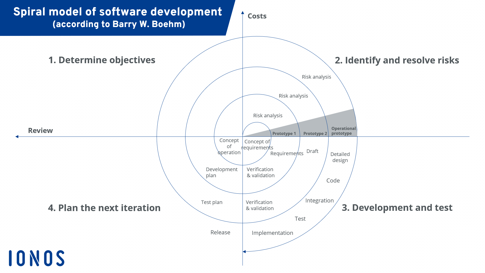
Spiral Model
The Spiral Model is a risk-driven software development process model that combines iterative development with the systematic aspects of the traditional waterfall model. It was introduced by Barry Boehm in 1986 to address the shortcomings of the waterfall model, particularly its inflexibility and inability to handle risks and changing requirements effectively.
Key Characteristics of the Spiral Model
- Risk-Driven Approach: Focuses on identifying and mitigating risks early and throughout the development process.
- Iterative Development: Involves repeated cycles or “spirals,” allowing for iterative refinement and continuous improvement.
- Customer Involvement: Encourages active participation of stakeholders and users to gather feedback and validate requirements.
- Phased Planning: Divides the development process into multiple phases, each focusing on specific objectives and deliverables.
- Flexibility: Adapts to changing requirements and project dynamics, making it suitable for complex and high-risk projects.
Phases of the Spiral Model
The Spiral Model consists of multiple spirals, each comprising the following four phases:
1. Identification (Planning and Requirements)
- Description: Identify objectives, alternatives, constraints, and requirements for the project.
- Activities:
- Define project objectives and scope.
- Identify potential risks and constraints.
- Gather and prioritize requirements.
- Develop a preliminary project plan.
- Deliverables: Project Objectives, Requirements Document, Initial Project Plan.
2. Design (Risk Analysis and Engineering)
- Description: Analyze identified risks and develop strategies to mitigate them. Design the system architecture and components.
- Activities:
- Conduct risk analysis and identify mitigation strategies.
- Develop system architecture and design specifications.
- Create prototypes or simulations if necessary.
- Plan for the next iteration.
- Deliverables: Risk Analysis Report, System Design Document, Prototype (if applicable).
3. Construction (Implementation and Testing)
- Description: Develop and test the software components based on the design specifications.
- Activities:
- Implement the software components and conduct unit testing.
- Integrate components and perform system testing.
- Validate the software against requirements and objectives.
- Document testing results and identified issues.
- Deliverables: Source Code, Test Reports, Validated Software.
4. Evaluation (Customer Evaluation and Planning for Next Iteration)
- Description: Evaluate the software with stakeholders and gather feedback for improvements and refinements.
- Activities:
- Present the software to stakeholders and gather feedback.
- Evaluate the project’s progress and assess remaining risks.
- Update project plans and requirements based on feedback.
- Plan for the next spiral, considering new insights and changes.
- Deliverables: Evaluation Report, Updated Project Plan, Refined Requirements.
Subsequent Spirals
Each spiral follows the same four phases, with increased refinement and expansion of the software as new features and improvements are implemented. The number of spirals depends on the project’s complexity, risk factors, and requirements.
Advantages of the Spiral Model
- Risk Management: Prioritizes risk identification and mitigation, reducing the likelihood of project failure.
- Iterative Refinement: Allows for continuous refinement and improvement, ensuring alignment with user needs and requirements.
- Customer Involvement: Engages stakeholders throughout the development process, ensuring their needs are addressed.
- Flexibility: Adapts to changing requirements and project dynamics, making it suitable for complex projects.
- Early Detection of Issues: Identifies potential issues and risks early in the process, allowing for timely mitigation.
Disadvantages of the Spiral Model
- Complexity: The iterative and risk-driven nature of the model can add complexity to project management.
- Resource Intensive: Requires significant time and resources for risk analysis, iterative development, and stakeholder involvement.
- Difficult Estimation: Estimating the project’s time and cost can be challenging due to the iterative and evolving nature of the model.
- Requires Expertise: Effective risk management and planning require experienced teams and skilled personnel.
When to Use the Spiral Model
The Spiral Model is best suited for projects with the following characteristics:
- High-Risk Projects: Projects with significant uncertainties, risks, or complexities.
- Complex Systems: Projects involving complex systems or innovative solutions where exploration and refinement are valuable.
- Evolving Requirements: Projects with evolving requirements and the need for flexibility and adaptability.
- Stakeholder Involvement: Projects where active stakeholder involvement and feedback are crucial for success.
Real-Life Example of the Spiral Model
Example: Development of a New E-commerce Platform
Problem:
A company wants to develop a new e-commerce platform to support online sales, inventory management, and customer engagement. The project involves complex features such as personalized recommendations, dynamic pricing, and real-time inventory tracking.
Application of the Spiral Model:
- Identification (Planning and Requirements):
- Define project objectives, including sales targets, user engagement metrics, and customer satisfaction goals.
- Gather initial requirements for product catalog, shopping cart, payment processing, and user authentication.
- Design (Risk Analysis and Engineering):
- Conduct risk analysis for potential issues such as security vulnerabilities, scalability challenges, and integration with third-party services.
- Develop the system architecture and design specifications, focusing on scalability and performance.
- Construction (Implementation and Testing):
- Develop and test the core features of the platform, such as product catalog and shopping cart functionality.
- Validate the software against requirements and gather feedback from stakeholders.
- Evaluation (Customer Evaluation and Planning for Next Iteration):
- Present the platform to stakeholders and gather feedback on usability, functionality, and performance.
- Plan for the next iteration, incorporating additional features such as personalized recommendations and dynamic pricing.
Subsequent Spirals:
- Iterate through the Spiral Phases:
- Continue refining the platform with new features and improvements based on stakeholder feedback and risk analysis.
- Conduct iterative testing and validation to ensure alignment with project objectives and user needs.
Impact:
The Spiral Model allows the company to manage risks effectively, adapt to changing requirements, and deliver a high-quality e-commerce platform that meets user expectations and business goals.
Conclusion
The Spiral Model is a powerful software development approach that combines iterative refinement, risk management, and stakeholder involvement to deliver high-quality software. By prioritizing risk analysis and iterative development, the Spiral Model ensures alignment with user needs and reduces the likelihood of project failure. Understanding the characteristics, advantages, and disadvantages of the Spiral Model enables development teams to select the best approach for their specific project needs, ensuring successful software delivery and customer satisfaction.